Free-Body Diagrams
Introduction
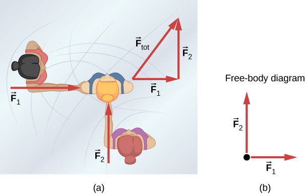
"Figure 5.3 (a) An overhead view of two ice skaters pushing on a third skater. Forces are vectors and add like other vectors, so the total force on the third skater is in the direction shown. (b) A free-body diagram representing the forces acting on the third skater."
Image Source here
A free-body diagram (FBD) is a pictorial representation of an object and all the external forces acting upon it. It's a crucial tool in physics for analyzing force problems and applying Newton's laws of motion. Mastering the creation and interpretation of free-body diagrams is essential for solving a wide range of mechanics problems.
Purpose of Free-Body Diagrams
- Visualize all forces acting on an object
- Simplify complex physical situations
- Aid in setting up equations for problem-solving
- Help identify action-reaction pairs
Components of a Free-Body Diagram
- The object of interest, usually represented as a point or a simple shape
- Arrows representing forces, with:
- Length proportional to the magnitude of the force
- Direction indicating the direction of the force
- Labels for each force
- Coordinate axes (when relevant)
Steps to Create a Free-Body Diagram
- Isolate the object of interest
- Draw a simple shape to represent the object
- Identify all external forces acting on the object
- Draw arrows representing each force
- Label each force
- Add coordinate axes if needed
Types of Forces Commonly Seen in Free-Body Diagrams
- Weight (W or mg): Always points downward
- Normal force (N): Perpendicular to the surface of contact
- Friction (f): Parallel to the surface of contact, opposes motion
- Tension (T): Along the direction of a rope or string
- Applied forces (F): In the direction of application
- Spring force (Fs): Along the axis of the spring
Common Scenarios and Their Free-Body Diagrams
1. Object on a Flat Surface
      N
      ^
      |
    --|--
   |     |
   |  *  |
   |_____|
      |
      v
      W
Forces: Normal force (N), Weight (W) If moving or about to move: add Friction (f) and Applied Force (F)
2. Object on an Inclined Plane
     N
      \
    |  \
 W  |   \  f
 |  |    \
 | \|     \
 |  *----->F
 |         \
 v          \
Forces: Normal force (N), Weight (W), Friction (f), possibly Applied Force (F)
3. Two Objects Connected by a String
   T    T
<----*---->*
     m1    m2
     |     |
     v     v
     W1    W2
Forces: Tension (T), Weights (W1, W2)
Example Problem: Block on an Inclined Plane
A 5 kg block rests on a 30° inclined plane. The coefficient of static friction is 0.3. Determine if the block will slide down the plane.
Step 1: Draw the free-body diagram
     N
      \
    |  \
 W  |   \  f
 |  |    \
 | \|     \
 |  *      \
 |          \
 v           \
Step 2: Identify and label forces
- Weight (W)
- Normal force (N)
- Friction force (f)
Step 3: Break down the weight vector
- W_parallel = W sin(30°) = mg sin(30°)
- W_perpendicular = W cos(30°) = mg cos(30°)
Step 4: Apply Newton's Second Law
- Along the plane: f = W sin(30°) for equilibrium
- Perpendicular to the plane: N = W cos(30°)
Step 5: Check if maximum static friction is exceeded
- f_max = μN = μmg cos(30°)
- f*max = 0.3 * 5 kg _ 9.8 m/s² * cos(30°) = 12.74 N
- W sin(30°) = 5 kg _ 9.8 m/s² _ sin(30°) = 24.5 N
Since W sin(30°) > f_max, the block will slide down the plane.
Common Mistakes in Creating Free-Body Diagrams
- Including internal forces
- Omitting forces
- Incorrect force directions
- Inconsistent scale for force arrows
- Forgetting to break down forces on inclined planes
Applications of Free-Body Diagrams
- Analyzing static equilibrium problems
- Solving dynamics problems with Newton's Second Law
- Understanding complex systems like pulleys and connected objects
- Analyzing forces in structures and machines
Practice Problems
-
Draw a free-body diagram for a book resting on a table. Then, draw a new diagram showing what changes if the table is accelerating to the right.
-
Create a free-body diagram for a person standing in an elevator that is accelerating upward.
-
Draw a free-body diagram for a car rounding a banked curve at constant speed. Assume the banking angle is sufficient to prevent sliding.
-
Two masses m1 = 2 kg and m2 = 3 kg are connected by a light string over a frictionless pulley. Draw free-body diagrams for each mass and use them to set up equations to solve for the system's acceleration.
-
A block is placed on a wedge, which is resting on a table. The wedge is then slowly pulled horizontally. Draw free-body diagrams for both the block and the wedge.